| klys | glad to hear you finally got a prompt, my condolences on the cache issues. | 03:40 |
|---|---|---|
| lkcl | klys: that's a kernel-exception prompt :) | 08:54 |
| lkcl | but it is actually interactive, which is the funny bit | 08:54 |
| octavius | lkcl, please have a look at the pinmux page (bug #762) when you have a chance. I'll be off for some driving, will be back later to respond | 12:32 |
| lkcl | octavius i've an investor meeting to prepare for | 13:40 |
| lkcl | octavius, wotcha. i just added banksel/pullup/pulldown to C4M JTAG TAP.add_io() function | 17:53 |
| * lkcl need tea | 17:54 | |
| octavius | Nice, thanks! | 17:54 |
| lkcl | you can ignore it completely for the GPIO-wb-peripheral for now | 17:57 |
| lkcl | because JTAG is a "pass-through". | 17:57 |
| lkcl | the idea of using banksel=7 isn't going to fly | 17:58 |
| octavius | Are you busy with the investor prep still? I mentioned on the wiki page to utilise the upper bit for JTAG control of the GPIO (because you might still want to use the lower two bank select bits for muxing peripherals during the test) | 18:01 |
| octavius | Ah apologies, haven't seen the bug updates, I'll read that now | 18:34 |
| lkcl | done | 18:34 |
| lkcl | yes, that's out. total disconnect. JTAG is a pass-thru, absolutely nothing to do with GPIO or its config | 18:35 |
| lkcl | however | 18:35 |
| lkcl | when it *is* added, it is added *in between* banksel, pullup, and pulldown | 18:35 |
| lkcl | exactly like i, o, and oe are, right now | 18:35 |
| lkcl | this does mean that there are two sets of MUXes between the IOs and the actual pads | 18:36 |
| lkcl | but... tough | 18:36 |
| octavius | Ah, so the GPIO block is really just a controller for the IOPad. And when bank is changed, the controller becomes a peripheral (like I2C) | 18:39 |
| octavius | We don't need the peripheral to feed *into* the GPIO block, because it is a separate component | 18:40 |
| lkcl | no, it's dual-purpose. | 18:47 |
| lkcl | purpose 1) | 18:47 |
| lkcl | a controller for the IOpad | 18:47 |
| lkcl | purpose 2) | 18:47 |
| lkcl | a means and method of connecting *BANK ZERO* to some wishbone-backed read/write "stuff" | 18:47 |
| lkcl | " And when bank is changed, the controller becomes a peripheral (like I2C)" | 18:48 |
| lkcl | not quite | 18:48 |
| lkcl | this again is down to accuracy of english language semantics | 18:48 |
| lkcl | when the bank is changed, *one* of the peripherals is directly connected to the IOpad | 18:49 |
| octavius | yeah | 18:49 |
| lkcl | not "the controller becomes a peripheral" | 18:49 |
| lkcl | "We don't need the peripheral to feed *into* the GPIO block" | 18:49 |
| lkcl | yes, it will | 18:49 |
| lkcl | for banks 1 and above, the following will be needed: | 18:49 |
| lkcl | * I/O/OE "in" | 18:49 |
| lkcl | * I/O/OE "out" | 18:50 |
| lkcl | i think | 18:50 |
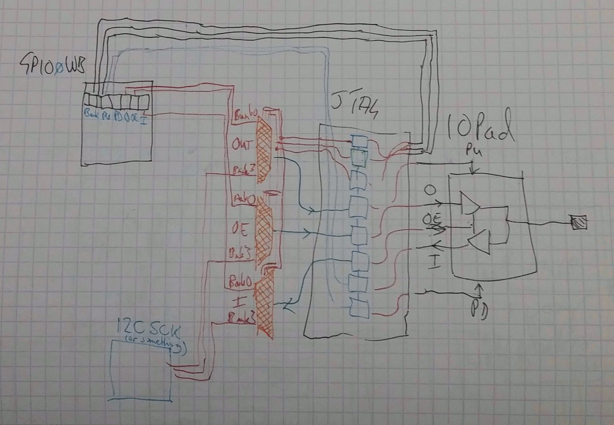
| lkcl | let's look at the diagram again | 18:50 |
| lkcl | https://libre-soc.org/pinmux/muxjtag2.png | 18:50 |
| * lkcl thinks | 18:50 | |
| octavius | To me it looks like there are two blocks | 18:50 |
| octavius | the GPIO | 18:51 |
| octavius | and the mux | 18:51 |
| lkcl | those muxes (in orange) are... mmmm | 18:51 |
| lkcl | weeeelll.... | 18:51 |
| octavius | hehehe | 18:51 |
| lkcl | yyeah actually it might be sensible to make them separate blocks | 18:51 |
| lkcl | what do you think? | 18:51 |
| octavius | I think separation will make it sane for testing XD | 18:52 |
| lkcl | i was thinking initially in terms of the (orange) muxes being actually inside the GPIO block | 18:52 |
| lkcl | ha, yes :) | 18:52 |
| lkcl | and smaller modules (therefore smaller graphviz diagrams) | 18:52 |
| octavius | Also, do you expect individual bank select per GPIO pin? Or a shared bank select for a block of GPIOs? | 18:52 |
| lkcl | both | 18:52 |
| octavius | Because that means 3 signals into JTAG *per* pin on top of what's already needed | 18:53 |
| lkcl | ok that's not quite accurate | 18:53 |
| lkcl | ok so let's imagine you have an SD/MMC peripheral | 18:53 |
| lkcl | the 4 data wires can have their direction reversed, but only all-at-the-same-time | 18:54 |
| lkcl | BUT | 18:54 |
| lkcl | the individual IOpads do not have "ganging" | 18:54 |
| lkcl | therefore, something needs to care of that "ganging" of the one OE fan-out to 4 OEs | 18:54 |
| lkcl | now | 18:54 |
| lkcl | in an FPGA situation, you would have the peripheral PHY code take care of this | 18:55 |
| octavius | Connect the 4 OEs before they come into the GPIO block? | 18:55 |
| lkcl | although on the "core" side you would have one OE direction input | 18:55 |
| lkcl | it is the *PHY* code which takes care of the fan-out to create 4x duplicate copies of that one OE signal | 18:55 |
| lkcl | thus you would have 4x (I/O/OE) on the *pad* side of the PHY | 18:56 |
| lkcl | and this is the kicker: | 18:56 |
| lkcl | every bank-sel'd set of I/O/OE pins *must* be *identical* to those of actually looking like they were *directly* connected to the IOpad itself | 18:57 |
| lkcl | therefore | 18:57 |
| lkcl | the muxer must *not itself* consider any kind of "ganging" of OE signals, at all | 18:57 |
| lkcl | it is *not* the GPIO mux's problem, nor is it the GPIO config's problem | 18:57 |
| octavius | The diagram muxjtag2 effectively shows just one pin. So for SD/MMC, you'd have 4 instances of that diagram, and it will be the periphal that will be responsible for controlling the i/o/oe. Is this not correct? | 18:59 |
| lkcl | yes it does | 18:59 |
| lkcl | 4 instances yes | 18:59 |
| lkcl | actually six | 19:00 |
| lkcl | CLK | 19:00 |
| lkcl | CMD | 19:00 |
| lkcl | D0 | 19:00 |
| lkcl | D1 | 19:00 |
| lkcl | D2 | 19:00 |
| lkcl | D3 | 19:00 |
| octavius | besides the point, that diagram is all that's needed, no? | 19:00 |
| lkcl | the last 4's OE signals are duplicated in a fan-out | 19:00 |
| lkcl | yes basically, it is | 19:00 |
| octavius | Or is there additional logic that's required? | 19:00 |
| lkcl | nnope | 19:00 |
| octavius | So as for what to implement: | 19:03 |
| octavius | parametrisable GPIO block that has outputs a layout of (i/o/oe/pu/pd/bank sel) for *each* GPIO | 19:03 |
| octavius | parametrisable mux block with i/o/oe inputs and bank select used for muxing | 19:03 |
| octavius | a top-level module that instantiates the above two, with a peripheral pin, and IO pad | 19:03 |
| octavius | also a JTAG chain, using you extension with bank sel and pu/pd | 19:04 |
| octavius | Once that works, test a parametrisable version | 19:04 |
| lkcl | 1) yes. | 19:05 |
| lkcl | 2) yes, although i strongly recommend the mux block take a dictionary of "stuff" by names that you can easily print out (and debug). don't do it as "lists with no identifying details". use the pinmux conventions or preferably actually use the pinmux data structures themselves if you can stand it | 19:07 |
| lkcl | (btw do use numbering in future so i can reply with the same numbering) | 19:07 |
| octavius | sure | 19:07 |
| lkcl | 3) yes, but it gets slightly complex when you think about how we did the jtag boundary-scan thing, but... yes, let's add that later | 19:08 |
| lkcl | 4) yes, which should in theory be possible to chain together easily and integrate into the code you did last month-or-so | 19:08 |
| octavius | Not sure what you meant by a "take a dictionary of stuff". I do want gtkwave to actually show a port of signals, but don't know what the examples might look like | 19:09 |
| lkcl | 5) oh i see... yes, do it hard-coded initially with a few peripherals as examples, like uart and i2c (because uart has tx rx and i2c has i/o/oe) and then make it more general. | 19:10 |
| lkcl | it means "use the same pinmux structures as used in the code written a couple of months ago" | 19:10 |
| lkcl | Ports? | 19:11 |
| lkcl | Resource! | 19:11 |
| lkcl | or the data structures in pinmux.py | 19:11 |
| octavius | Instead of "bank_sel$1", actually group a set of signals | 19:11 |
| lkcl | no | 19:11 |
| lkcl | instead of | 19:11 |
| lkcl | banksel = [list, of, utterly, incomprehensible, crap] | 19:11 |
| lkcl | banksel = {'I2C0_SDA': ...} | 19:12 |
| lkcl | if you don't have names ("dictionaries of stuff") you will go insane trying to understand what the bloody hell you were doing when wiring up the actual Muxes | 19:12 |
| lkcl | this *needs* to be regular and blindingly obvious | 19:13 |
| lkcl | it's going to be complicated as hell to wire up | 19:13 |
| lkcl | one of the reasons for that is because IOpad "O" and "OE" signals are not actually "outputs", they are *inputs*! | 19:14 |
| octavius | It is obvious, I just don't get how you create it. Can't just be a basic python dict? I saw syntax of "SubSignal("name",etc.)" | 19:14 |
| lkcl | yes i'd do a basic python dict | 19:15 |
| lkcl | not piss about creating classes | 19:15 |
| lkcl | but this is the point: | 19:15 |
| lkcl | although you need the Muxes to, technically, receive their inputs as a list | 19:15 |
| lkcl | please make sure that the wires are actually named | 19:16 |
| lkcl | what i don't want to see is this: | 19:16 |
| lkcl | banksel = [list,of,incomprehensible,crap] | 19:16 |
| lkcl | mux[0] = banksel[crapola0] | 19:16 |
| lkcl | mux[1] = banksel[crapola1] | 19:16 |
| lkcl | ... | 19:16 |
| octavius | {"port0": Signal(blah blah)}, like that? | 19:16 |
| lkcl | yyeees | 19:16 |
| lkcl | or | 19:17 |
| lkcl | more | 19:17 |
| octavius | Does gtkwave automagically give it names | 19:17 |
| lkcl | {"port0": Signal(name="port0", blah blah) | 19:17 |
| lkcl | *no it doesn't* | 19:17 |
| lkcl | that's the point | 19:17 |
| octavius | And if I have a layout? | 19:17 |
| octavius | Same thing but repeated? | 19:17 |
| lkcl | if you have a layout you get a partial name | 19:17 |
| lkcl | Record(name="fred", layout=[("blogs", 1)]) | 19:18 |
| lkcl | will create gtkwave traces | 19:18 |
| lkcl | fred_blogs | 19:18 |
| lkcl | not fred | 19:18 |
| lkcl | not blogs | 19:18 |
| lkcl | fred_blogs | 19:18 |
| lkcl | try it | 19:18 |
| lkcl | actually a Record is probably a good idea | 19:19 |
| octavius | Thanks | 19:19 |
| octavius | I'll do that | 19:19 |
| lkcl | where the Record *must* be of width banksel | 19:19 |
| lkcl | but its contents (the names of the layout) can be named after their PHY names | 19:19 |
| lkcl | soo... | 19:19 |
| lkcl | Mux0 = Record(name="port0", layout=[("gpio_a0", 1), ("uart0_tx", 1), .... ]) | 19:20 |
| lkcl | see how that works? | 19:20 |
| lkcl | it's got all of the naming info, which will trickle through to the gtkwave traces | 19:21 |
| lkcl | BUT | 19:21 |
| lkcl | if you did it as | 19:21 |
| lkcl | Mux = Signal(banksel) | 19:21 |
| lkcl | or | 19:21 |
| lkcl | Mux0 = Record(name="port0", layout=[("mux0", 1), ("mux1", 1) .... ]) | 19:22 |
| lkcl | how the hell would you know what was what? | 19:22 |
| lkcl | that's what i mean by "don't use crapola lists-of-stuff" | 19:22 |
| octavius | I think I see it, but I'll need more experimentation. I'll try adding names to layouts first | 19:22 |
| lkcl | use dictionaries (or Records) which *actually* have the *actual* names in them | 19:22 |
| lkcl | great. perfect | 19:22 |
| octavius | Don't really understand how dictionaries will help with gtkwave, but records definitely | 19:23 |
| octavius | Or are dictionaries more for debugging the code itself, not looking at the sims? | 19:23 |
| lkcl | not with gtkwave, but with understanding the code | 19:24 |
| lkcl | yes | 19:24 |
| lkcl | and doing "print" statements to find out what the hell's going on | 19:25 |
| lkcl | then relate it *back* to the gtkwave | 19:25 |
| octavius | Wow, adding a prefix to a layout is night and day XD | 19:26 |
| lkcl | duh :) | 19:33 |
| *** analognoise1 is now known as analognoise | 21:50 | |
Generated by irclog2html.py 2.17.1 by Marius Gedminas - find it at https://mg.pov.lt/irclog2html/!